When you are feeding cables through a boat, it is often necessary to remove bulky connectors to fit the cable through tight spaces, or you may need to extend the cable and fitting proper mating connectors is ideal. Soldering connectors can be fiddly and crimping requires a specialist tool that many people do not have, so using a solderless, quick fit RF connector is very tempting.
However, I learnt a lesson today that I hope others can learn from. I had not come across this particular type of connector before (see image above) and the idea is that you place the coax cable firmly up inside the connector where a sharp center pin presses in to the inner conductor of the cable. Then you tighten down the small screw shown in the image above and it cuts through the outer insulation and makes contact with the outer, shield conductor of the cable. At first sight, this seems a very clever idea but as I was to discover this type of connector can create more problems than it solves.
The boat that I visited had one of our AIT2000 Class B Transponders on which was giving a high VSWR reading in the proAIS2 diagnostics software. The VSWR reading is one of the built-in self tests of the AIT2000 where it measures the power it sends to the antenna and also measures the “reflected” power that comes back down the aerial. In an ideal world all of the power sent to the antenna should be transmitted in to the air, but this is never the case and a small amount is always reflected back to the AIT2000. If there is an antenna fault or a short or open circuit in the antenna cable then the VSWR reading will be very high (>5:1) and trigger an alarm.
On this particular boat, there were a number of these quick fit connectors used to extend the AIS antenna, but they appeared to be well made so I started by quickly connecting a spare VHF antenna directly to the AIT2000. Voila, on the next AIS transmission (every 3 minutes when stationary) the VSWR reading came right down to a very healthy 1.2:1. The installed AIS antenna was mounted on the mast so replacing it would be a pain, so just to be sure I thought I would check the extra piece of antenna cable that had been added to the cable. A quick DC continuity and isolation test showed a short between the inner and outer of the extension cable.
On closer examination of the quick fit connectors, I found that removing one of them, the short disappeared. My only conclusion was that either the small screw that is intended to just make contact with the outer shield had been over tightened shorting the inner and outer conductors or that blunt wire cutters had been used and some poorly cut strands of the shield had shorted to the inner. Any way the fault had been found and I quickly rejoined the “Quick Fit” connector to the cable. Just to be sure I repeated the continuity and isolation test and this time it showed the short had gone BUT there was no continuity on the inner connection.
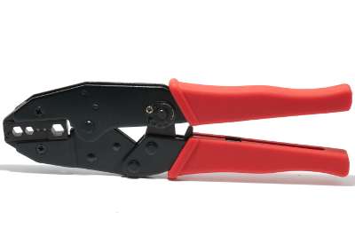
In total I tried remaking the “Quick Fit” connectors three or four times and on every occasion there was no continuity on the center conductor and in the end I gave up and replaced them all with crimp connectors which I have never had a problem with. You might have to spend £10-£15 on a crimp tool (see below) but if you are regularly doing RF connections or you simply want the best possible connection then I would definitely recommend the crimp connectors.


