You can also download this Tech Note (00036) from the Support Area of our Website.
Once an AIT2000 has been installed and operating correctly for some time, the most common causes of failure are the external connections i.e. Power, VHF antenna and GPS Antenna.
The first step is to test the Power Supply Connections
If, when you apply power to the transponder by turning on the circuit breaker or switch, you get no LEDs light up, then you most likely have a power connection problem. Make sure that any circuit breakers or fuses in the power supply circuit are OK and then measure the voltage across the Red (+) and Black (-) wires on the transponders power/data cable. If there is not a good supply voltage present of between 11v and 14.5v then you have a wiring problem.
If the supply voltage is good, it is worth remaking the red and black wire power connections to the AIT2000 as the crimp or terminal block connections on these small gauge wires can be difficult to make and, if poorly made with the wrong gauge connector, can often be less reliable than larger gauge wire connections.
The AIT2000 will power up in receive only mode, when plugged in to a computer’s USB socket, with no external power applied. If the unit is failing to power up from the external power supply connections, try plugging the USB lead into a PC and see if the AIT2000 powers up – red and yellow LEDs should light.
If the power connections are all OK, the transponder will start its power up sequence during which the LEDs should light as follows;
1) Green LED will come on briefly.
2) All four LEDs should flash once.
3) Just the Yellow LED should illuminate.
4) The yellow LED will stay on until the GPS gets its first fix and the transponder transmits its first AIS position report. At this point (usually within a few minutes of power up) the yellow LED will go OFF and the green LED will come ON.
5) The green LED will now stay on for the majority of the time and indicates that everything is OK and that the transponder is transmitting and receiving correctly. You may occasionally see the yellow LED come ON if the transponder tries to transmit but another vessel has taken its time slot or the GPS position is temporarily lost, but this is the exception and for >90% of the time the green LED should be the only LED illuminated.
If the Yellow LED has stayed on after 20mins of operation or the Red LED has turned ON, then a fault condition has occurred which will need fault finding.
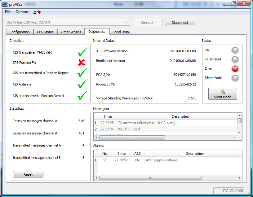
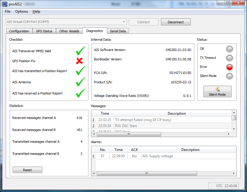
If you have a PC with the proAIS2 software installed, it is strongly recommended that you connect it to the transponder now. When you run the proAIS2 software and connect to the transponder, the most useful page is the “Diagnostics” tab. Here you can see a lot of useful information about what is happening inside the transponder including any active Alarms.
The following screen shot is taken from proAIS2 connected to an AIT2000 that is working correctly. Note the five green ticks (see image below) that indicate the results of five key status checks.
Even if the power connections are OK and the transponder is powering up, it is possible that the supply voltage is low – particularly after a long passage in a sail boat. The Low Voltage Alarm is triggered at around 9.6v – see screen shot below.
As soon as the supply voltage drops below 9.6v the AIT2000 stops transmitting, triggers an “AIS Supply Voltage” Alarm and the RED LED illumninates.
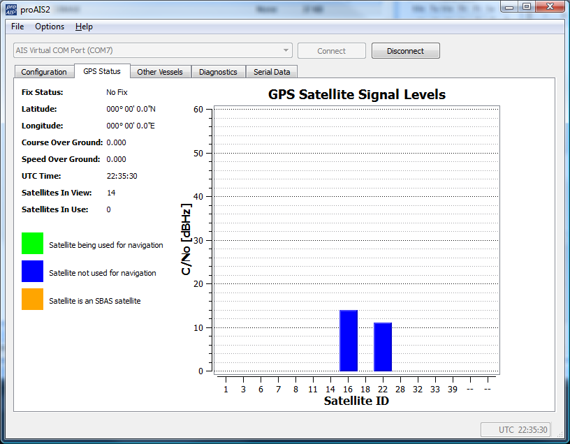
The most common cause of the transponder not transmitting (Yellow LED continuously on), is no GPS fix.
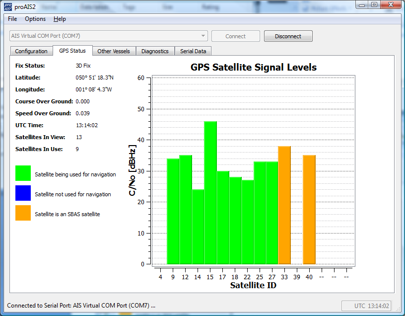
To check the GPS reception, click on the “GPS Status” tab.
If the GPS is good, then you should see a screen similar to the one above.
Note that the signal levels are all strong (>20) and displayed in green to indicate that they are good enough for navigation. The Yellow signals are SMAS (satellite based augmentation system) satellites and are used to get improved differential GPS accuracy.
The image above was actually taken with no antenna connected. If you are still seeing a screen like this after the AIT2000 has been on for a few minutes, then the GPS inside the AIT2000 may have a fault or the GPS antenna/cable may be defective.
The only conclusive way to tell if the fault is due to the AIT2000 unit or the GPS antenna is to replace the antenna for another known good antenna.
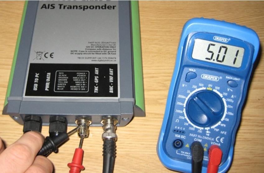
The only other test that can be done is to check if the AIT2000 is properly creating a 5v DC voltage that is required to supply the GPS pre-amplifier in the antenna. The procedure to do this is detailed below – note that the photos show an earlier AIT1000 unit but the process is the same;
1) Disconnect the GPS antenna from the AIT2000.
2) Using a Multi-Meter set to DC voltage, test for a 5v signal between the inner and outer connector of the AIT2000’s TNC connector as shown in the image opposite.
3) If there is no 5v signal, then the AIT2000 must be assumed to be faulty.
4) If there is a 5v signal, then replace the existing GPS antenna with a known good replacement GPS antenna.
If after connecting the known good GPS antenna, proAIS2 still shows the same low or non-existent GPS signals, then the AIT2000 must be at fault and will need to be returned to Digital Yacht for repair.
Is the splitter you are using compatible?
If the power supply is good and the GPS is working correctly, but the AIT2000 is not transmitting (RED or RED and YELLOW light on continuously), then there may be a problem with the AIS/VHF antenna. If you are using a splitter to connect the boat’s existing VHF antenna to the transponder, ensure that the splitter is definitely recommended for use with a transponder and is not one of the simpler/cheaper splitters that is only suitable for connecting an AIS receiver.
Whilst fault finding the transponder it is recommended that you disconnect the splitter and connect the VHF antenna directly to the transponder to prove that the splitter is not causing a problem with the AIS transmission and reception.
Returning to the “Diagnostics” Tab of proAIS2 again, see image below, pay particular attention to Voltage Standing Wave Ratio (VSWR) value which should be between 1:1 and 3:1 in a typical installation. The AIT2000 will stop transmitting, turn on the RED LED and display an “AIS Antenna VSWR Fault” alarm if the VSWR value is 5:1 or higher.
VSWR
The VSWR is a measurement of the amount of power being sent to the antenna and how much gets reflected back. In an ideal world, all of the power transmitted to the antenna will be transmitted into the air, but no installation or antenna is perfect and so some power will be reflected back to the AIT2000. If the amount of power is too much, then damage could occur to the AIT2000 and so this VSWR value is very important.
It should be noted that VSWR mainly affects your transmission range and even installations with a very high VSWR can still be receiving lots of AIS targets, so AIS reception alone is not a suitable measurement of your AIS transponder/antenna installation.
If you are getting a VSWR of > 5:1
Check all antenna connections and remake any connections that look bad or corroded. Ensure that the antenna cable has not been cut, melted, compressed or damaged in any other way. If it is a new installation make sure that the antenna cable has not been lengthened or shortened.
The only conclusive way to test whether the VSWR fault is the antenna or the AIT2000, is to swap the antenna for a known good antenna – perhaps using a spare emergency VHF antenna. If the new antenna gives the same high VSWR readings then you have to assume that the AIT2000 is at fault but more often than not it is the antenna or installation that is at fault in these high VSWR situations.
If the AIT2000 is operating correctly (continuous GREEN LED) then you can be 99.9% sure that you are transmitting your position correctly. A Class B Transponder transmits a signal based on the following specification;
1) Transmit Power = 2 watts (less than a hand-held VHF)
2) Transmit Range = 7-8 Nautical Miles (maximum typical range)
3) Transmit Rate = Every 30 seconds if SOG > 2knots and every 3 minutes if SOG < 2knots
4) Static Data Transmit Rate = Every 6 minutes regardless of speed
Check you are being seen
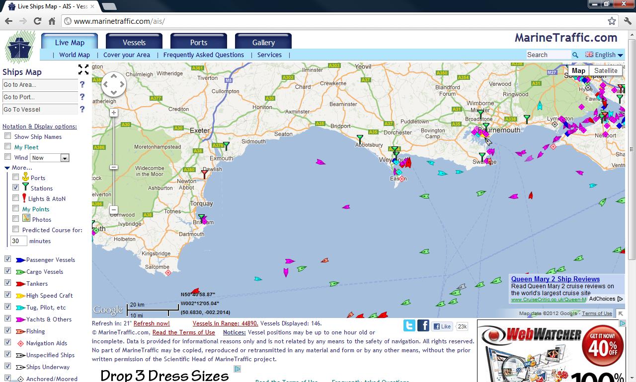
The best way to test if an AIS transponder is transmitting is to ask someone else in the same marina if they can see you on their AIS system. Alternatively, you might be able to use an on-line AIS service like Marine Traffic but this depends upon their coverage in your area. On the Marine Traffic website you can display the receiving stations by clicking on the “More” option and then tick the “Stations” setting (see below).
You need to be within 7-8 miles of a Green “Active” Receiver for your new Transponder to be detected and it also takes some time for your vessel to be recognised, logged in their system and displayed on their website.


