


At this time of the year, with people getting their boats ready for the season, adding new bits of kit and powering things up after a long winter layup, we get lots of enquiries about NMEA 2000 installations and accessories. One particular customer, had a serious NMEA 2000 network cabling issue and in supporting him in his hour of need, we created some new notes on how to create an NMEA 2000 test lead and use it to test a new or existing NMEA 2000 network.
If you have an old or spare NMEA 2000 cable kicking around in your “come in handy” box, then put it to good use and create your own NMEA 2000 Test Lead. Assuming your cable is a Male to Female cable, you can actually create two test leads from the same cable, by simply cutting it in half, stripping back the outer insulation and fitting the five wires inside (Red/White/Blue/Black/Shield) to a piece of terminal “chocolate” block – as shown below.

The Male Test Lead will actually be the most useful, as the majority of “back bone” connections are female, so you will be able to plug the Male Test lead in to any of these connections. The Female Test lead will be useful for connecting power to a “bus powered” NMEA 2000 device for firmware updating or configuration.
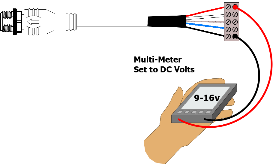
For the following tests we will be using the Male Test lead and a multi-meter to measure the NMEA 2000 Supply Voltage across the Red and Black power wires and to make sure the network is properly terminated by measuring the resistance between the Blue and White Data wires.
NMEA 2000 Supply Voltage Test
The NMEA 2000 network should be powered from a 12v supply and depending upon the number of devices on the network and the amount of power they take from the network, you may find voltage drops along the network. In extreme cases this can result in some devices not getting the proper 9.0v to 16.0v DC Supply voltage as specified in the NMEA 2000 specification.
You can use the NMEA 2000 Test lead to plug in to the network at various locations and test the supply voltage. In a well designed NMEA 2000 network the voltage drop should never be more than 1.5v. So if the supply voltage is 12.5v then you should never measure less than 11v at any point in the network.
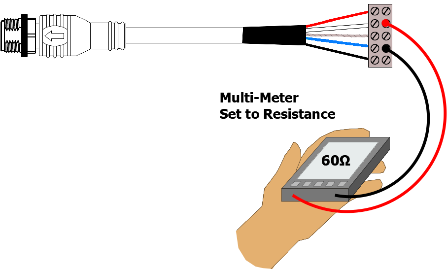
NMEA 2000 Correct Termination Test
The NMEA 2000 network should be properly terminated with a 120 Ohm resistor at each end of the backbone. No terminators, 1 terminator or more than two terminators can adversely affect the data signals and so it is important to test that your NMEA 2000 network is terminated correctly.
Two terminators, give a parallel resistance reading of 60 Ohms and this is what you should read. Plug the test lead in to any spare socket on the NMEA 2000 network and with the NMEA 2000 Network’s power removed, do a resistance test between the Blue and White Data wires of the NMEA 2000 test lead. You should measure 60 Ohms +/- 5%.
For more information on NMEA 2000 networking, we have created a useful guide which you can read by clicking here.
Using NAVDoctor to fully test an NMEA 2000 network
The two tests above are important basic tests to check the electrical integrity of your NMEA 2000 network, however with so many NMEA 2000 devices now being installed on boats, data and interoperability issues can also arise and if you wish to be able to more fully test and diagnose NMEA 2000 networks, our NAVDoctor NMEA 2000 Diagnostic tool is a good investment as this video will illustrate….


